aaronse.github.io
Low Rider CNC 3
The LowRider3 is the V1 Engineering version of a CNC router that can handle up to full sheet material! If the MPCNC is not big enough for you this picks up where that left off.
.jpg)
Key Points
-
Most parts can be 3D printed. To save from shipping or printing large parts the machine can be partially assembled to cut them itself.
-
Easily Removable from the table for storage or portability.
-
Inexpensive hardware store conduit is the recommended X rail. Rails ranging from 23.4mm to 25.4mm will work. This saves considerable cost over the LR2.
-
Many tool options, in terms of functionality and brands. Blank DIY mount files are available.
-
Full Y and Z axis squaring, leveling, and Z probing are available for excellent precision and accuracy.
-
Works with any 5 driver board. 4 driver boards can be used but some automation, one axis dual endstops, will be lost.
-
Can be used with Marlin, RepRap firmware, GRBL, FluidNC, or others.
.jpg)
Geometry
-
This CNC router can handle any length (within reason), the Y direction is only bound by your table length.
-
The single Y rail keeps the machine properly constrained while maintaining ease of use. Two rails are extremely difficult to align, and fully constrained rails do not allow for easy removal of the machine.
-
Width (X axis or “Beam”) should always be the shorter axis.
-
The Z direction (height) is best kept to 80mm. This allows for 1.5” of cutting depth, that is a lot. If you need to cut more than 1.5” deep this is not the CNC for you. Now if you need to cut a few millimeters off really thick material (facing a slab), this can be a great machine for that. You want to keep the machine as low as possible and make the table surface adjustable, drop table. This keeps the Material Removal Rate very high. The answer is not making a taller machine.
-
This router is most rigid when working near the table surface, opposite of most conventional gantry CNC machines. So the lower the axis the more rigid the machine.
.jpg)
License
This work is licensed under a Creative Commons Attribution-NonCommercial-ShareAlike 4.0 International License.
More details to my loosened restrictions can be found here on the home page.
.jpg)
Files can be found at the links below
- Printables.com
- Printables.com Link
- Thingiverse Printed parts files:
- Thingiverse.com Link Coming soon!
.jpg)
!!! info Previous build “LR V2” Version two instructions are here
Parts Needed
Printed Parts
Buy a set here, V1 Shop.
Or print your own. No supports needed, keep the default orientation. PLA is recommended for ultimate rigidity, other filaments should be evaluated for rigidity. 2-3 walls rectilinear infill. Thicker layers since these are large parts, no more than 80% nozzle diameter to keep overhangs working.
| QTY | File Name | Infill | Comment | Link |
|---|---|---|---|---|
| 1 | LR Core | 35% | ||
| 1 | X Drive Mount | 30% | ||
| 2 | Y Drive | 30% | ||
| 2 | Z Drive | 30% | ||
| 4 | Temporary Strut | 30% | ||
| 1 | Front Rail Roller | 30% | ||
| 1 | Rear Rail Roller | 30% | ||
| 1 | Bearing Wheel Bracket Front | 30% | * See note below - Optional Version | Link |
| 1 | Bearing Wheel Bracket Rear | 30% | * See note below - Optional Version | Link |
| 1 | Z Stop | 30% | ||
| 1 | Z Stop M | 30% | ||
| 6-8 | Brace -Choose one size- | 30-50% | * See Brace Note below | |
| 6-8 | Hose Hanger | 30% | Same number as braces, Optional part | |
| 1 | X Tensioner | 30% | ||
| 1 | XZ Plate Left | 70% | * See XZ note below - Can be milled | Shop - DXF |
| 1 | XZ Plate Right | 70% | * See XZ note below - Can be milled | Shop - DXF |
| 1 | Front Y Belt Holder | 30% | ||
| 1 | Front Y Belt Base | 30% | ||
| 1 | Front Y Belt Holder Right | 30% | ||
| 1 | Front Y Belt Base Right | 30% | ||
| 1 | Y Tension Block Rear | 30% | ||
| 1 | Y Tension Base Rear | 30% | ||
| 1 | Y Tension Block Rear Right | 30% | ||
| 1 | Y Tension Base Rear Right | 30% | ||
| 8-14 | Rail Block -Choose one size- | 30% | * See Rail block note below | |
| Optionally Printed | ||||
| 2 | YZ Plate | 50% | Best as a milled part | Shop - DXF |
-
Optional Version- You can use 58-62mm X 25mm with the option brackets. The wheels might provide for a smoother rider over a rough table or debris with the downside being a bit of “give” and the possibility of the Wheels steering a non parallel build. The bearings should be more precise and make for a more forgiving build. Wheels Spacers
-
Brace note- Print the end two braces with 50% infill and oriented so you can have the top facing out on each end, and the rest with 30%. 2’ wide builds need 6 total, 4 foot versions need 8 total. One every 200mm (8”) or less. Recommended US 3/4” EMT = 23.4mm = Brace 23p4 that is the suggested size for US based builds.
-
XZ Note- Can be a flat part. Milled or Purchased. If you do use a flat part you will need to print both “XZ Leadscrew Stub Right” and “XZ Leadscrew Stub”. These also need 70% infill.
-
Rail Block note- You want these with no larger than 200mm (8”) or less gap between them. Recommended US 1/2” EMT = 18.1mm = Rail Block 18p1.3mf. You will need 8 for a 4’ build and 14 for a 8’ build.
Tool Mounts
Recommended Makita 700 series router (available in many countries with slightly different model numbers), tool mount and dust shoe.
DeWalt 611, Tool mount and dust shoe.
Build your own, CAD and step files.
Board Boxes
Blank Box, DIY your own case, Fusion 360 CADlink.
Flat Parts
Strut Plates
The Three Strut plates were designed to be up to 6.35mm (1/4”) thick. Hardboard or any similarly rigid materials work best here.
Here are the pre-made most common Strut Plate sizes.
4’ Strut PLate Plate CAD/Fusion360
2’ Strut PLate Plate CAD/Fusion360
If you choose to adjust these to fit your build the only thing to know is you want no more than 200mm (8”) between the braces. Start with whichever CAD file is closest to your desired size and edit the first sketch.
YZ Plates
The YZ Plates can be nearly any thickness. Again here, rigidity is key. 1/2” (12mm) MDF is a great choice. Much thicker than that and you will need to clearance some for the coupler. At 16.5mm and thicker you will need to counter bore for the M5 nuts or get longer screws.
YZ Plate DXF Mirrored set YZ Plate DXF, just to make it easy to mill up a set. YZ Plate STL, If you want to try and print it.
XZ Plates
The printed XZ plates (when printed in PLA) prove to be more rigid than 1/2” MDF. The only way to get any more rigidity is going to metal. If you choose to make your own, here are the guidelines.
The M5 screws provided with the kit can handle up to 9.5mm thick plates and anything less than that. Anything above and you will need to counter bore the heads.
The M3 screws provided with the kit need 6.35mm to 7mm plate thickness. If you go thinner you will needs washers, to go thicker you will need to counter bore the heads.
Specialty Parts
You can buy most of the Specialty Parts and hardware here, V1 Shop
| QTY | Description | Comment | Link |
|---|---|---|---|
| 1 | Control Board | 5 driver minimum | Shop – Amazon |
| 5 | Steppers, Nema17 | 20mm+ shaft length | Shop – Amazon |
| 3 | stepper wire extenders | Shop – Amazon | |
| 3 | Pulleys 16T 10mm | 10mm GT2 16 Tooth | Shop – Amazon |
| 6 | Idlers Smooth 20T | 20T Smooth 5mm Bore | Shop – Amazon |
| 8M | Belt GT2 10mm | See Calculator, no steel belt | Shop – Amazon |
| 5 | Endstops | Shop – Amazon | |
| 14 | 6082rs Bearings | Shop – Amazon | |
| 2 | T8 Leadscrew & nut | 110mm or larger | Shop – Amazon |
| 2 | Coupler | 8mm to 5mm | Shop – Amazon |
| 4 | Linear rails MGN | MGN12H 150mm | Shop – Amazon |
| 1 | Power Supply | 12-36V Board dependant 36W+ | Shop – Amazon |
| * | Thread locker | Optional for grubs screws | Shop – Amazon |
| * | Lube | Optional for idlers and linear rails | Shop – Amazon |
| * | Vac Hose | Optional any 1.5” OD Vacuum hose should work | – Amazon |
As an Amazon Associate, I earn from qualifying purchases.
Hardware
This is what is needed for a 4’ x 8’ (1.2M x 2.4M) build. You will need more or less depending on what size you build.
| QTY | Description | US Equivalent |
|---|---|---|
| 14 | M8 x 40mm | 5/16” x 1.5” |
| 14 | M8 Nylock nuts | 5/16” Nylock |
| 100 | M5 x 30mm | None |
| 100 | M5 Nylock | None |
| 40 | M3 x 10mm | None |
| 10 | M2.5 x 12mm | None |
| 24 | 3mm x 12mm Wood/metal | #4 x 1/2” Wood or Sheet metal screws |
| *22 | M4 x 12mm+ Wood/metal | #8 x 1/2”+ Screws to mount things to your table |
- Not included in the hardware kit.
LR2 to LR3 hardware differences for updating your build
|QTY |Description |US Equivalent | |—–|————————|———————————————–| |14 |M8 x 40mm |5/16” x 1.5” | |94 |M5 x 30mm |None | |94 |M5 Nylock |None | |36 |M3 x 10mm |None | |10 |M2.5 x 12mm |None | |24 |3mm x 12mm Wood/metal |#4 x 1/2” Wood or Sheet metal screws | |22 |M4 x 12mm+ Wood/metal |#8 x 1/2”+ Screws to mount things to your table| |4 |150mm MGN12H Rails |Shop Link|
Table
Any flat surface you can screw into will work great. Basic torsion box tables can be a step up in terms of long term stability with not all that much added complexity. A Removable spoil board section that can be easily replaced comes in handy as well.
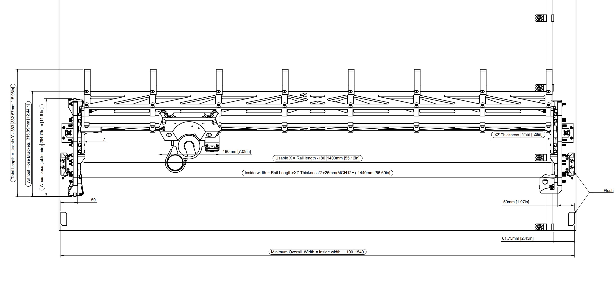
footprint *to do rail position Belt block positions
Calculator for table, rail, and belt lengths.
Assembly
Core Assembly
.jpg)
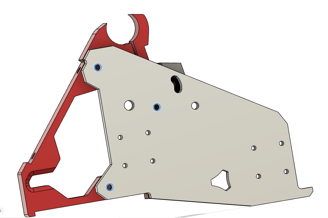
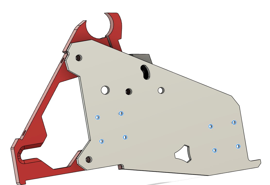
- LR Core, and six M5 nuts.
.jpg)
- Press these 6 nuts in place.
- If they are not snug, use some loctite or glue to keep them in place, or mount your tool mount now loosely.
- The 7th hole is a spare for future expansion packs.
.jpg)
- Bolts, 6082RS bearings and nuts for the next step.
.jpg)
- Snug up these 6 bolts and make sure everything still moves freely.
- These last two bolts control how much tension the core has on the Beam.
- Lightly seat these nuts and wait to set the tension until you have the beam ready.
.jpg)
- Get your Micro switch ready along with some M2.5 screws.
.jpg)
- Notice the lever orientation.
- Lightly set the M2.5 screws. If they strip out, add a drop of glue or thread locker to the threads and they should stay seated when it dries.
X Drive
.jpg)
- This section uses the X Stepper Mount, M5’s, and Idlers.
.jpg)
- Assemble as shown with the nuts down, very lightly seating the nuts.
- The inside nut fits in a small groove in the printed part.
- Make sure the Idlers spin freely.
.jpg)
- Add the pulley to the stepper 1-2mm up from the base.
- Tighten the flat grub screw first and then the next.
- Threadlocker or LocTite is recommended.
.jpg)
- Assure the pulley is centered with the idlers when assembled.
.jpg)
- Make sure to orient the wire out, as shown.
- Snug the stepper in place with M3’s
.jpg)
- Add the stepper assembly to the Core.
- Make sure the M5’s engage the nuts properly, If there is any sign of binding, back out and try again.
- If for some reason the nuts spin, use a small flat head screw driver to pin it in place as you tighten.
.jpg)
- Snugged in place.
.jpg)
- Tuck the wires into the groove and you can secure them at the top with a wire or cable tie.
- Now is a good time to add your touch plate wires if you are using one.
- If you are concerned you can add a piece of tape in between the screw holes but any tool mount should also do the trick here.
- Soon this part is going to be buried behind a router and a hose, so admire it now. Looks good, right?!
Side Plate Assemblies
.jpg)
- Z drives, steppers, M3 screws.
.jpg)
- Pay attention to wire routing here.
- Snug up the M3 Screws
.jpg)
- Y drives, Idlers, M5’s
.jpg)
- Seated, not snug. Screws are axles here.
- Nuts facing down.
- Make sure idlers are very free to spin.
.jpg)
- Add the pulley to the stepper. 1-2mm gap next picture has a visual check.
- Tighten the grub screw on the flat shaft surface first then the other screw.
- LocTite is recommend on all grub screws.
.jpg)
- Make sure the pulley teeth are centered with the idlers.
- Snug The stepper in place with the M3 Screws.
- Wires should face one in each direction (mirrored), just like the Y drives.
.jpg)
- Microswitches, M2.5 screws.
.jpg)
- Make sure the lever faces out (up in this picture).
- Switch away from the stepper wires, route wires together (for now).
- Gentle with the tiny screws threading into the printed part. Seated, no more.
- If you do happen to strip out the screw holes, a drop of nearly any glue or LocTite on the threads will fix it.
.jpg)
- Orientation, mirrored sets.
.jpg)
- Z Stop & Z Stop M, wired endstops, M2.5mm screws.
.jpg)
- Notice the direction of the switch levers
- Tuck the wires nicely into the grove and make sure not to pinch them when installing them later.
- Gentle with the small M2.5 screws.
.jpg)
- T8 nut, and 1-2 M3 screws.
- In the following steps, you will either be using the printed XZ plates, or XZ lead screw stubs.
.jpg)
- One screw is plenty as it is just there to stop the brass nut from spinning.
.jpg)
- A completed XZ printed plate.
.jpg)
- With milled XZ plates, you will need to attach the stubs to the plate with an M5.
.jpg)
- The nuts gets seated in the printed stub.
- Align the angled surfaces of both parts.
.jpg)
- Orientation of the stubs and XZ plates.
.jpg)
- The MGN12H bearing blocks get attached to the XZ plate.
- If you are using the printed version, M3x10mm screws will fit.
- If you are using a milled part follow the guidelines for thickness. Only use washers if necessary.
.jpg)
- Now is a good time to assure the linear guides are moving freely. If not, loosen the 4 small screws on the end of the bearing block a full turn. Move the bearing block back and forth and tighten the screws back up.
- You can add a touch of a light oil or dab of the superlube, but it should not be necessary.
- Keep the stops in the end until they are mounted to the YZ plates to avoid tiny bearings everywhere.
.jpg)
- With the rails mounted, make sure they are parallel by measuring how far apart they are at the top and bottom of travel at the ends.
- Snug up the M3’s. LocTite is not a bad idea here.
.jpg)
- You will need to add three M5’s to the holes shown here. Actually, you only need the lower two, but just to be safe drop them all in for now.
.jpg)
- Use the small wood screws to attach the rails to the YZ plate.
- Start attaching the rails in the middle, one screw each. Loosely.
- Once you have a screw in each rail you can remove the stops.
- Keep adding screws and checking for smooth motion as you go.
- The hole in the XZ plate is there to let you access the middle screw.
- If all is going well, snug up the wood screws into the YZ plate. Gentle here. Do not strip out the MDF/wood. It doesn’t take much.
.jpg)
- Add the Z drive wires facing the back.
- Use M5 screws here and snug it up a bit.
Z End Stop
.jpg)
- Attach Z Stop & Z Stop M parts with M5 screws and nuts.
- Test to make sure the micro switch clicks before the XZ plate hits the top.
- If not, the printed parts are vertically slotted to allow Z stop height to be adjusted, and/or can bend the microswitch arm to adjust. IF bending, ensure the switch’s tiny trigger still functions, so, bend the arm at the kinky end.
.jpg)
-
The endstop wires will run through a small slot in the Y drive. Make sure they are free to move and not pinched.
- Keeping the printed parts aligned with the plates keeps it looking nice.
- Make sure the screws are snug so the switches do not move.
.jpg)
- Insert the Y drive. It goes in with a 90 degree twist. Should be plenty of room when XZ plate is moved aside, just. Caution: XZ plate doubles as a finger guillotine as the assembly weight increases throughout the build.
- Make sure the endstop wires are free moving.
-
Snug the screws.
- Wire routing, each side should run towards the back of the plate.
- Cable tie points on the Y and Z drives.
- Wire sleeve is optional, but looks nice here. Or, leave them exposed to make it look more complicated to your audience. Everyone loves a person with a big brain.
Wheels
.jpg)
- 608rs and bolts, Bearing Wheel Bracket Front & Rear.
.jpg)
- Preferred “wheels”
- Seat the bolt so the head and nut are making contact, but do not tighten. This is just an axle.
- Pay attention to the bolt orientation. The nut goes in the deeper side.
.jpg)
- Optional Wheel brackets Link
- Use spacers to prevent over tightening
- Seat the bolt, but no need to over-snug it.
.jpg)
- Wheels installed; bolts in, nuts out. Snug these four screws.
.jpg)
Rail Rollers
.jpg)
- Front and Rear Rail Roller, bolts and bearings.
.jpg)
- Insert the bearings, and seat the bolts.
- No need to snug as these are just axles.
- Bolt orientation is important here. One bolt is facing up and the nuts is tricky to slide into the top.
.jpg)
- Side Plates are done!
- Roll them around on your table making motor noises to make sure they work right.
Beam Assembly
- If you already have your strut plates cut, use this as a loose guide.
- Install the strut plates loosely at first to get everything aligned then go back and snug them all up. Install the strut plates in this order; front face (with top and bottom rail clamping), bottom, and sloped back (with the optional vac hose hangers).
.jpg)
- Building the beam includes the X rails, braces (optionally two with higher infill for the ends), temporary strut plates, and a lot of M5’s.
.jpg)
- Fit your rail together. Make sure the end two plates have a top printed surface facing out. This makes for a more perfect mating surface as mesh bed leveling can leave an odd surface on the bottom.
- Sliding the braces on your rail is preferred over snapping them in. This keeps a sharp clamp tip.
.jpg)
- Next step is to add the front temporary strut plates.
- Remember, initially you will be leaving the screws loose.
- Roughly space the rest of the braces equally down the beam.
.jpg)
- Loosely add the rest of the front screws, lightly engaging the Nyloc just so they do not fall out while making these first cuts.
.jpg)
- Very loosely add the bottom screws, again, lightly engaging the Nyloc.
.jpg)
- Now add the rear temporary strut plates and optionally, the hose hangers.
- You can snug up the temp plate screws and the hose hanger screws.
- If you lay the beam on its face as shown in this picture you can tell if the beam is twisted or not.
.jpg)
- Now go back and snug up the front clamps.
- The key here is just lightly engaged, There will be a gap, and the rails will be able to spin if you try.
- The clamps do not do very much other than account for slight rail size differences. Do not over tighten.
- The only catch here is make sure the screw faces make contact and the nuts make contact with the printed part. It is possible to thread the screw in and the nuts not actually be all the way in, eventually they would loosen up. You can thread the screw all the way in and keep turning to lightly ream out the screw hole if needed before adding the nuts.
.jpg)
- Add the LR-Core to the beam and set the tension of the lower two bolts.
- Too loose and the core can move and you will hear bearings clicking on the rails.
- Too tight and you will feel the LR-Core hesitate over each brace. More is not better here.
- Typically, little to no extra tension is needed and it is best just to seat the nuts gently.
- Last check is to make sure the X rails do not stick out further than the braces, at least on the bottom rail.
.jpg)
- You can add the side plates using the 6 screws.
- Snug these up.
- Make sure both sides move up and down pretty freely, as long as gravity pulls them all The way down you are good to go here.
- Measure the heel and toe distances across your machine, make sure they are equal. If not adjust the end clamps.
- Best practice is to make robot noises while you move it up and down (feel free to tag me in your video when you do #V1LR3).
X Belt
.jpg)
- Run your X belt through the X Drive.
- It is a good idea to run it as shown and cut it when you know exactly how long to make it.
.jpg)
- To secure the ends you can make a small fold, or use a 4-5 tooth cutoff, and pull it back into the slot.
- Just make sure it does not interfere with the YZ plate when you move the Z axis all the way up.
.jpg)
- Leave a bit of room to pull it out if needed.
.jpg)
- For the X tensioner, insert belt through the side, then loop around and back on itself (out the side again) to set the length.
- If you have a hard time getting this right, you can draw a little line on the top of your belt to see which way you need to go. Each tooth is two millimeters (1/16”), so it is very easy to adjust.
- Make sure to seat the nut into the tensioner.
.jpg)
- Add the X tensioner to the XZ plate and set the tension just below where it makes a sound when you pluck it.
- Make sure to leave ~4mm (1/8”) or more gap between the plate and tensioner to adjust this later if needed.
.jpg)
- Add your tool mount of choice.
- Snug up the vacuum side of the mount and leave the stepper side loose. This is the side you will always use to set the tension.
- Make sure the wires are free to move behind the mount and not pinched.
.jpg)
- Stand back and admire what you have accomplished. Feel free to get a loved one or neighbor and tell them you designed the entire thing from scratch.
Y Rail
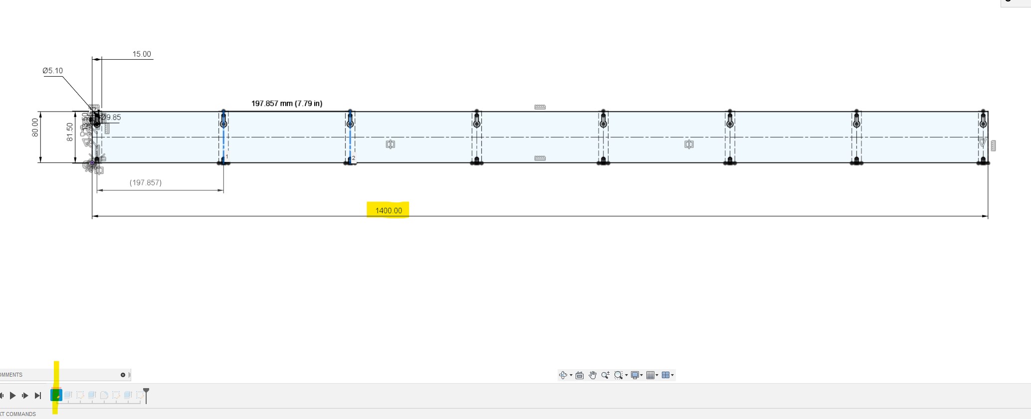
- The calculator dimensions are for edge to edge table use. If you added extra width divide it by two and place your “Front Y Belt Holder Base Right”.
- From there the edge of your Rail blocks get placed 61.75mm in from that, that line gets followed all the way down the rail.
.jpg)
- I pre-drill all the rail block holes in the center to have some adjustment if needed.
- The center of the rail block slots are 44.7mm in from the line set in the previous step for a total of 106.45mm in from the edge of your Y belt block.
.jpg)
- Place the rail blocks no further than 200mm (8”) apart.
.jpg)
- You can measure out the other Y belt holder block or wait to use the fully assembled machine to mark it with the Y drive. The Y drives are flush with the rail blocks.
.jpg)
- Another view of that.
.jpg)
- Place the Y tension bases inline with the front blocks and far enough in to act as a hard stop not to drive your machine of the edge of the table.
- 30mm in from the edge is good. More in from the edge (88mm) if you do not want your hose holders to moves past the edge of the able.
Wire Routing
.jpg)
- Wire routing is pretty free form with lots of options. Here is how I do it.
- If you have not cut your strut plates yet you will have a chance to revisit the wiring or you can route it so you do not have to remove it at all.
- Labeling your wires is great idea.
- For more specific wiring info please see the “Control” tab in the main menu, and then select your board.
.jpg)
- Be sure to tape or secure any connections.
- I find it best to start by running the shortest wire first.
- You can see how the Z endstop and Y stepper wires are ran down and secured.
- The wires then run under the Z stepper and get secured again.
.jpg)
- The extensions will be needed for the wires on the rail side.
- You can route the wires around the back and into the hose holders (easy to work with later).
- Or you can run the wires into the beam and secure them in there.
- Make sure you have full range of Z motion and the wires don’t catch anywhere.
.jpg)
- Full shot of the wires ran and the excess folded over in the hose holders.
- The X axis wires need to have full range of motion so that means securing them just short of the half way point.
.jpg)
- I temporarily added the power supply on the wire bundle.
- After the strut plates are cut, I prefer to mount it inside the beam.
.jpg)
- Now you can add the lead screws.
-
Make sure the Z axis has full range of motion and does not hit the coupler when at the bottom of motion.
Y Belt
.jpg)
- When running the Y belts Feed the belt through the Y drive and secure into the front blocks first.
- Loop the belt over with enough room to remove it later if needed.
.jpg)
- The rear blocks get a nut inserted and are quick release and adjustable.
- The right tension is tight, but just before it starts to sound like a bass guitar, if plucked. You should be able to remove the block still as well. If you have a way to check, 6-10lbs tension is what you’re looking for.
.jpg)
- Rear block assembled.
.jpg)
- Now do the other side.
.jpg)
- You nervous yet? It is time to fire it up! No need to make your own noises anymore, the machine will do it for you. See, I thought of everything! —
Getting Started, cutting your strut plates
At this point you should be able to power up and give your build a little test move. Depending on how your machine is built, you can use your control screen, repetier host, other software over USB, or over the air.
Here is a quick overview of a basic movement test.
Initial Squaring
To square the machine you need to mark 4 points and measure the diagonal. This is how we set the Y axis homing to square the machine relative to the rail. You will probably need to repeat this a couple times to get it under 1mm difference.
You can cable tie a pen to the vacuum mount as shown below, or here is a pen mount that fits on most router bodies. V1 Printables
You can also automate this process with Jamie’s “Squareness Marks” test.
- Start with G92 X0 Y0 Z0 - Check this box and where the pen tip is will be 0,0,0. I suggest starting the pen just above the paper.
- Z level for pen-down - Make this number more negative if you find some of your marks are not hitting the paper, but you want as light a touch as possible.
- Z level for pen-up - You can go as high as you need to not drag the pen tip.
- Feedrate - This is set at a safe travel rate.
- Extents - This is where you set the dimensions of your table. The further apart the marks the more accurate your table will be.
.jpg)
- I use tape, so I can be sure I am using the correct mark.
- Home the X and Y axis.
- Use the Z axis to mark a small dot at 0,0.
.jpg)
- Now drive the machine to your X axis furthest point (or very close to it).
- Use the Z to mark the dot.
.jpg)
- Drive to the Y extreme and repeat the process for the back two corners.
.jpg)
- Now measure the diagonals to the best of your ability. Note the longer one, and subtract to find the difference. Under 1mm is very good.
If you are over 1mm in difference you can use the terminal on your SKR Pro or a USB connection and repetier host to add a homing offset. “M666 Y0.5” will move your Y1 stepper 0.5mm away from the stop block after it homes. “M666 Y-0.5” will move your Y2 stepper away instead. You want to move the longer dimension side away from the block. A good first guess is the difference in your measurements (or you can use a trig calculator and add a bit because your end stops are further away than the dots). Now Use “M500” to save it to the EEPROM. Re-home X and Y and test it again.
Z Leveling
.jpg)
- Z leveling is a bit easier than the Y axis if you have a touch plate. You can also use any sort of block or piece of paper as a feeler gauge.
- We are only looking for the difference here.
.jpg)
-
Home all three of your axis.
-
Touch plate - If you are using the touch plate, you probe by using G38.2 Z0. When it gets there, take note of the current Z position. Then move it up and over to your X axis extreme and probe again, taking note of the Z axis position. Take the difference and adjust the side that moved furthest.
-
Feeler Gauge - You will drive your Z axis down until you just make contact with the touch plate and take note of the current Z axis position. Repeat this for the other end of the X axis. Take the difference and adjust the side that moved furthest.
.jpg)
-
You adjust by running “M666 Z0.5” the number is in millimeters. Save with M500 after each adjustment home all axis and start check your work.
-
These numbers are counting down from 200, so 120 is further away than than 130. Start by adjusting 0.2mm more than your difference.
Making the Strut plates
At this point you should be ready to make some cuts. To be certain it all goes as planned, you can make a test cut in high density foam, or simply making an air cut. To make an air cut you, just home your machine above the table and run the gcode. This lets you watch that it moves as you would expect it to and doesn’t snag or have any faults in the code.
Gcode making - TODO
The three strut plates should be 6.35mm (1/4”) or thinner MDF or similarly rigid material. You will want to cut each plate as close to the side of your build as you can to assure your build has the rigidity to do so.
.jpg)
-
Getting ready to make your first cuts all starts with loading the material.
-
Make sure the edge is behind your Endmill in the Y direction and parallel with the edge in the X direction.
.jpg)
- Checking the front and back edges relative to the table. (To the rail would be a more proper measurement)
.jpg)
- Secure the material and make sure your means will not interfere with the core as it passes over. I use screws with large heads.
.jpg)
- This is what a finished cut looks like. All parts are held in place with small tabs of material that can be cut with a saw or utility knife.
- Do this two more times.
Disassembly
.jpg)
.jpg)
.jpg)
.jpg)
.jpg)
.jpg) —
—
Final Assembly
.jpg)
- Measure the heel and toe distances across your machine, make sure they are equal. If not adjust the end clamps. Problems can arrise if your rails are too long after you install the strut plates.
.jpg)
.jpg) —
—
Vacuum
.jpg)
Size, options, routing, grounding. *to do
Quick release coupler for 1.5” hose.
Using the machine.
Firmware
Dual endstop LowRider “DualLR” firmware recommended for ultimate accuracy and precision. This requires at least a 5 driver control board. This allows you to align the Y axis and Z axis using dual endstops.
The standard MPCNC firmware will work with any board on the LowRider if you are not using endstops or wired in series (using a 4 driver board). You will just use hardstops like the LR2 did.